Click Here for Principle of Operation
The 24-Inch HYGE system is designed to simulate the effects of a collision in acceleration rather than a deceleration mode. The standard 24-inch HYGE has 1,000,000 pounds (4.5 Meganewtons) of thrust. The HYGE’s design provides extremely repeatable and reproducible acceleration pulses, enabling accurate simulation and modeling of crash conditions. The HYGE system has proven its repeatability/reliability over time. Systems over 40 years old routinely demonstrate repeatability of better than +/- 2% today.
Applications
The 24-inch HYGE systems are in active used for a variety of automotive and aircraft safety testing applications. Some typical HYGETM applications include:
- Testing of air-bag systems, including firing circuits, sensors, squibs and air bag units
- Side impact testing.
- Testing auto seat belts, including belt design, webbing, hardware and anchors.
- Testing auto interior parts, such as dash boards, bolsters and head liner trim.
- Side air-bag testing
- Biodynamic testing of human subjects to determine biological limits and effects of shock.
- Used as a velocity source for barrier auto crash testing. This involves testing components such as bumper systems and front and rear panels.
- Shock testing of automotive components sold as separate items, such as stereos and cellular telephones.
- Testing of child restraint seats and booster seats.
- Shock testing of automobile electronic control modules.
- Testing of aircraft seats, seat belts and components.
- Testing effects of cargo inside aircraft cargo hold during extreme conditions
- Shock testing of military, space systems and components.
- Simulation of mine blast to US and European specifications.
Features and Benefits
- Proven Accuracy – capable of simulating actual crash pulses to within +/-2%.
- Repeatability – better than +/-2%, even after more than 40 years and 30,000 firings.
- Reproducibility – pulses can be accurately reproduced on different HYGETM systems, enabling sharing of test programs and results between components suppliers and OEM’s.
- Versatility – The HYGETM has the structural integrity and thrust capability to perform side impact tests which are not possible with “light rail” type systems. Lightweight sled allows testing of light trucks and sport utility vehicles.
- Universally Accepted –testing standard for FASS and FAA requirements.
- Mechanically Simple – only 2 moving parts.
- User Friendly operating software.
- Experienced installation, training and service team.
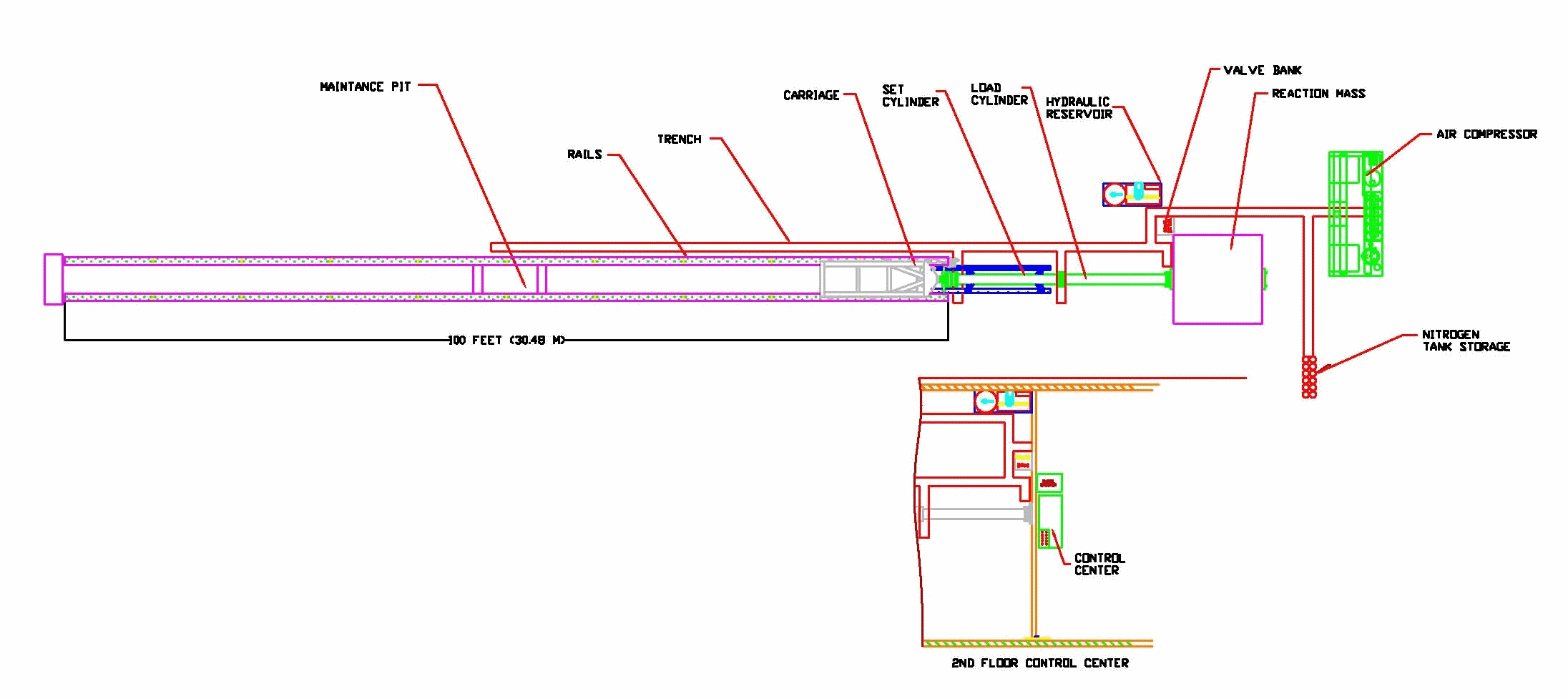
Standard System Configuration
The 24-inch HYGE system consists of the following major components:
- The Actuator, which has a stroke length of 6 feet (182.8 cm)
- The Rail System and Carriage.
- The Pneumatic System, which provides pressurized gas for firing the piston.
- The Fluid Transfer System, which provides fluid to vary the volume of the cylinders.
- The Control Center, which contains the valve system, computer control and operator station.
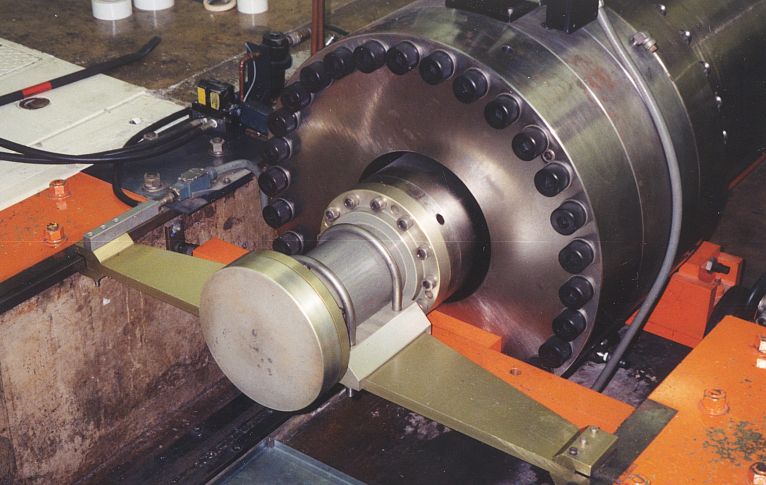
Actuator
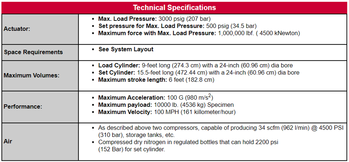
 The 24-inch Actuator consists of two cylinders; each with a 24-inch (61 cm) bore. The total length of the Actuator is 30.7 ft (9.4 m). It is mounted on the face of a reinforced concrete foundation block (reaction mass).
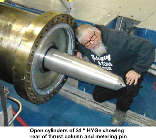
The purpose of the metering pin is to throttle the amount of energy transferred to the Carriage at any given time during firing, thereby determining the shape of the acceleration pulse. A particular crash situation, will have a waveform determined by actual crash tests or by computer modeling. The metering pin is machined to produce the desired pulse shape for a given payload gas pressure/volume parameters. In addition, aspects of the waveform can be varied through changes in the gas volumes and pressures in each cylinder prior to firing. A half-sine metering pin is provided with the system.
HYGETM, INC. offers a metering pin design program, which enables the engineer to enter the characteristics of the desired waveform and automatically generate the required metering pin profile.
Rail System and Carriage
The HYGETM rail units are manufactured in 10-foot (3m) sections. A 100-foot (30.4M) rail assembly is supplied with the system as standard. The rail sections are installed approximately 4-feet (130cm) apart. Additional rails are available in 10-foot sections.
The carriage is approximately 5 feet (1.5 m) wide by 12 feet (3.7 m) long, and weighs approximately 3600 pounds (1630kg). It has a maximum payload capacity of 10,000 pounds (4,500 kg). The carriage has pneumatic brakes, which operate on the rails through brake pads. The service brake pressure is set by the operator to establish brake force throughout the acceleration phase and subsequent slowdown to stop. The Carriage is also provided with an emergency brake control system with an on-board pressurized tank, valve and switch. This provides a secondary system to stop the Carriage if the initial service brake pressure is insufficient. The maximum braking force is approximately 34,000 lbf (151,200 N). The thrust and brake system combine to produce very regular waveforms.
Pneumatic System
The compressed air module consists of multistage compressors, capable of producing 34 scfm (962 l/m) @ 4500 PSI (310 Bar). 18 storage tanks (1270 cubic inch each), a dryer, pulsation tank, condensing trap and blow-down tank with filter and oil separator are provided, complete with piping and electrical components on a steel framework ready for installation.
Fluid Transfer System
The Hydraulic Reservoir and Transfer system provides the means of varying the volume of the cylinders. By adding or removing fluid, the thrust produced by a given set and load pressure combination may be adjusted to achieve the desired test conditions. The system includes reservoir tanks, pumps and the required valves, controls and sensors. The necessary hydraulic hoses are provided to connect the transfer and reservoir system to the actuator.
Control Center
The automated control system provides complete automation of the preparation and firing sequence. A graphical user interface allows the operator to visually determine the status of the system at a glance, and program firing parameters using a menu system. The control center also offers a convenient interface to a variety of supporting equipment.
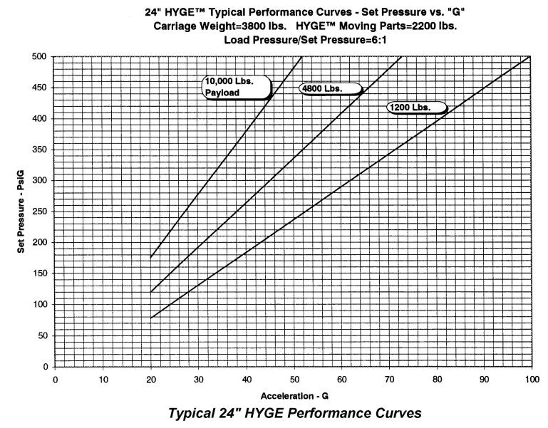
System Performance
Typical System Layout