 Shock testing is not new; in order to study the effects caused by shock waves to an object many devices have been created. Precise study requires a testing device that will produce a shock which is predictable, reliable and repeatable.
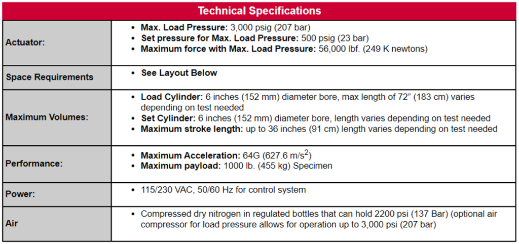
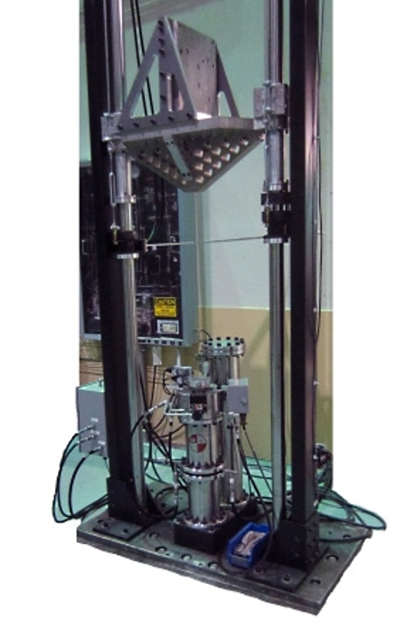
The 6-Inch Vertical HYGETM system is designed to simulate the effects of a shock in an acceleration rather than deceleration mode.
The 6-Inch Vertical HYGETM system develops thrust up to 56,000 lb f (249 KN), it can also produce acceleration values to several hundred times gravity for milliseconds duration and it can produce several different waveforms at various levels.
The 6-Inch HYGETM Vertical system consists of a 6” (15.2 cm) ID set cylinder attached to a primary load cylinder this is secured to the mounting base. An optional mounting base can allow for additional load cylinders.
The thrust column is attached to the thrust piston for the stroke. This system design provides extremely repeatable and reproducible acceleration pulses, enabling accurate simulation.
The system has proven its repeatability over time. HYGETM systems over 40 years old routinely demonstrate repeatability of better than +/- 2%.
The test specimen is either mounted to a light weight carriage that is attached to a rail system or directly mounted to the thrust column. Pneumatic brakes are mounted on the carriage. Additional rail sections and different carriage sizes are available.
The HYGETM system offers precise control of pulse shape, excellent test repeatability and universal acceptance within the automobile manufacturing community.
Methods of Controlling Accelleration
Acceleration of test specimen of the HYGETM shock test is governed by the thrust and the specimen mass. The thrust is equal to the difference in pressure between the set chamber and load chamber, times the net piston area exposed. To provide the control necessary to produce a given acceleration waveform or shock patter a specific metering pin attached to the underside of the thrust piston projects through the orifice into the load chamber. The contour of the pin meters the gas flow through the orifice, regulating the acceleration and making the utilized thrust precisely repeatable.
Deceleration External
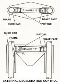 Deceleration can be controlled externally, by means of a rail and carriage system.
The rail system includes a carriage on which the test specimen is mounted, this is guided by rails.
Prior to firing the carriage is held in contact with the thrust column.
Once the unit has been fired and the acceleration phase is over, the carriage and specimen are brought to rest with brakes that are mounted to the carriage.
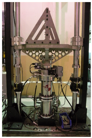
Deceleration Internal
 With internal deceleration the set chamber is subdivided into two chambers with a deceleration orifice.
Part of the set chamber is filled with hydraulic fluid and there is a deceleration metering pin attached to the thrust column.
The small test object is mounted to the end of the thrust column. Once fired and a distance is traveled the fluid is forced through the deceleration orifice bringing the thrust column and test object to rest.
Major Components
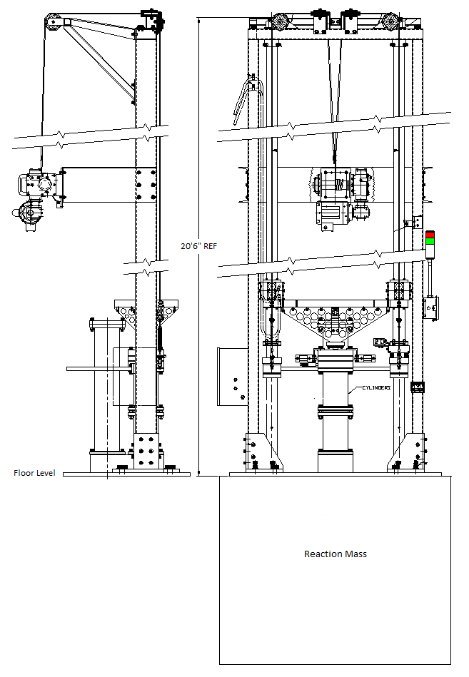
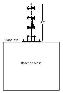
 Rails: the rails guide the carriage and specimen during deceleration in order to maintain as low a deceleration level as is desired. Rails can vary from 8 to 20 feet. Ideally the rail system should be as long as the overhead clearance permits. Actuator can be located in pit to increase usable rail length and lower specimen carriage to floor level.
Carriage: supports specimen mounting onto a fixture bolted to the carriage. The carriage assembly includes pneumatic brakes. There are optional emergency brakes for firing the carriage with decreased primary brake pressure. There is an included carriage return mechanism.
Foundation: the recommended foundation is six-foot cube.
Actuator: the internal working parts of the HYGETM unit including the thrust piston, thrust column, seal rings and orifice plate (or plates if deceleration is ordered). There is also an optional safety interlocking device or lock yokes.
Control System: the touch screen control center contains a graphical representation of the system. The control system features an intuitive user interface that provides controls for every automatic function of the system, from the automatic filling of the system pressure to the storing of successful test parameters data. Click here for more information on the Control System.
Distribution Center: the distribution center contains all of the valves, regulators, power supplies, etc.
Compressed Air: The 6” HYGETM system can be operated from compressed nitrogen bottles. The optional air compressor decreases nitrogen usage by using compressed air on the load side of the system, allowing for pressures up to 3,000 psi to be used (extending the range of operation from 40,000 pounds (178 K Newtons) thrust to 56,000 pounds (249 K Newtons) thrust).
The video below shows a 6” vertical HYGETM system with actuator cylinders mounted below floor level, with Sled and 50 foot rail system.
Applications
Systems are in use worldwide for a variety of automotive and aircraft safety testing applications. Some typical applications include:
- Aircraft ejection seat testing
- Hand held equipment and small appliances
- Hemets and protective head gear
- Components and subassemblies
Features and Benefits
- Proven Accuracy – capable of simulating actual crash pulses to within +/-2%.
- Reproducibility – pulses can be accurately reproduced on various systems, enabling sharing of test programs and results between components suppliers and OEMs.
- Versatility – can perform velocity and acceleration tests.
- Mechanically Simple – Very few moving parts.
- Low Cost Energy – 2200 psi nitrogen
System Performance
The system is capable of producing a wide variety of shock pulses. There is a standard half sine wave meting pin supplied with the system. The pulse may be modified by adjusting the HYGETM system firing parameters.