Click Here for Principle of Operation
The 12-Inch HYGETM system is designed to simulate the effects of a collision in acceleration rather than a deceleration mode. The standard 12-inch HYGETM has 225,000 pounds (1 M newton) of thrust. The HYGETM design provides extremely repeatable and reproducible acceleration pulses, enabling accurate simulation and modeling of crash conditions in non-destructive fashion. A given pulse can be accurately produced on any 12-Inch HYGETM system, enabling component suppliers and OEM manufactures to share testing programs and data interchangeably. The HYGETM system has proven its repeatability/reliability over time. Systems over 40 years old routinely demonstrate repeatability of better than +/- 2%.
12 Inch System Applications
Over 50 12-inch HYGETM systems are in active use worldwide for a variety of automotive, military, aircraft safety testing applications. Some typical HYGETM applications include:
- Testing of air-bag systems, including firing circuits, sensors, squibs and air bag units
- Side impact testing.
- Testing auto seat belts, including belt design, webbing, hardware and anchors.
- Testing auto interior parts, such as dash boards, bolsters and head liner trim.
- Side air-bag testing
- Biodynamic testing of human subjects to determine biological limits and effects of shock.
- Used as a velocity source for barrier auto crash testing. This involves testing components such as bumper systems and front and rear panels.
- Shock testing of automotive components sold as separate items, such as stereos and cellular telephones.
- Testing of child restraint seats and booster seats.
- Shock testing of automobile electronic control modules.
- Testing of aircraft seats, seat belts and components.
- Shock testing of military and space systems and components.
- Simulation of mine blast to US and European specifications.
Features and Benefits
- Proven Accuracy – capable of simulating actual crash pulses to within +/-2%.
- Repeatability – better than +/-2%, even after more than 40 years and 30,000 firings.
- Reproducibility – pulses can be accurately reproduced on different HYGETM systems, enabling sharing of test programs and results between components suppliers and OEM’s.
- Versatility – The HYGETM has the structural integrity and thrust capability to perform side impact tests which are not possible with “light rail” type systems. Lightweight sled allows testing of light trucks and sport utility vehicles.
- Universally Accepted –testing standard for FASS and FAA requirements.
- Mechanically Simple – only 2 moving parts.
- User Friendly operating software.
- Experienced installation, training and service team.
Standard System Configuration
The 12-inch HYGETM system consists of five major components:
- The Actuator, which has a stroke length of approximately five feet (1.5 m).
- The Rail System and Carriage.
- The Pneumatic System, which provides pressurized gas for firing the piston.
- The Fluid Transfer System, which provides fluid to vary the volume of the cylinders.
- The Control Center, which contains the valve system, computer control and operator station.
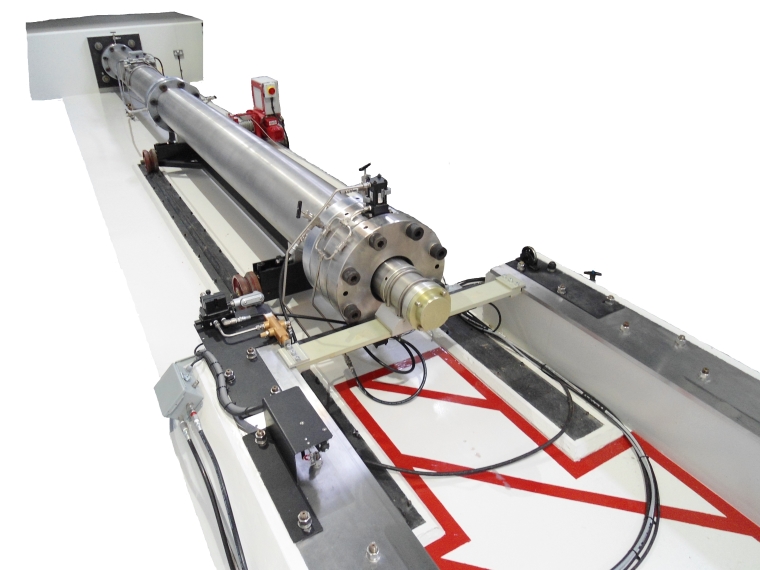
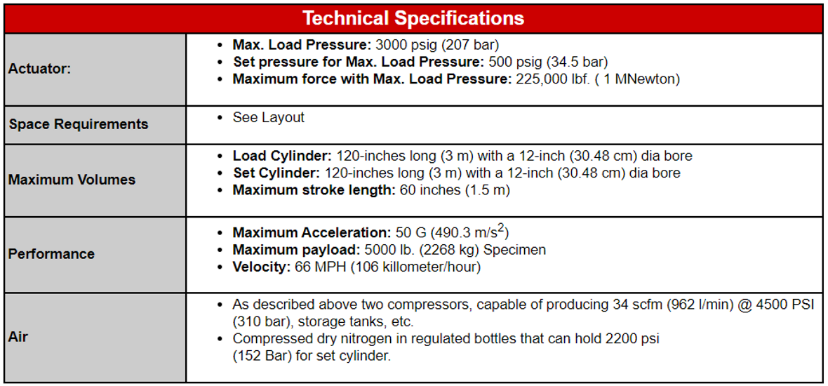
Actuator
The 12-inch HYGETM actuator consists of two 12-foot long (3.6m) stainless steel cylinders; each with a 12-inch (30.48 cm) bore. The shock tester is mounted on the face of a reinforced concrete foundation (reaction) block. All HYGETM units use a metering pin is to throttle the amount of energy transferred to the carriage at any given time during firing, thereby determining the shape of the acceleration pulse. A particular component, in a particular crash situation, will have a waveform determined by modeling or by actual crash tests. Each metering pin is machined to produce the desired pulse shape for a given specimen and set of crash conditions. In addition, aspects of the waveform can be varied through changes in the set cylinder volume, load cylinder volume and the gas pressures in each cylinder prior to firing.
HYGETM offers a metering pin design program, which enables the engineer to enter the characteristics of the desired waveform and automatically generate the required metering pin profile.
HYGETM offers a modular metering pin.
Rail System and Carriage
The rail units are manufactured in 10-foot (3m) sections. A 100-foot (30.4m) rail assembly is supplied with the 12-inch HYGETM system as standard. The rail sections are installed approximately 3-feet (100cm) apart on concrete piers or flush to floor at the users discretion. Extra rails are available in 10-foot increments. The rail sections are precision ground on the top, bottom and inside edge to provide guidance for the carriage. Each rail section includes the necessary anchor bolts, bolt positioning template for locating the bolts in the concrete foundation, and the necessary nuts and washers. The rails may be mounted flush with the floor, or raised. An optional maintenance pit, which is about 15 feet long by 2 feet deep, may be installed as part of the foundation instillation.
General Options
-
- Honey Comb End Barrier – Honeycomb over travel barrier may be installed at the end of the rail system to protect the carriage in the event of carriage overrun.
- Velocity Measuring Accessory – This is a photo eye assembly with display to measure carriage velocity.
- Carriage Movement System – Replaces the standard cable hoist system to allow for easy movement of the carriage interlocked to prevent firing the system while the carriage is still attached.
Carriage Options
-
- Standard Steel Carriage
- Light Weight Carriage Sled
- Turret Sled
- M-SIS Side Impact
- Side Dynamic
- Delayed Braking System – Can be added to sleds for Whip Lash/ Increased rise time of leading edge.
- Custom Carriages for specific user applications
Pneumatic System
The compressed air module consists of two compressors, capable of producing 34 scfm (962 l/min) @ 4500 PSI (310 bar), storage tanks, a dryer, pulsation tank, condensate trap and blow down tank with filter and oil separator are provided, complete with piping and electrical components all mounted on a steel framework, ready for installation.
Fluid Transfer System
The hydraulic fluid reservoir and transfer system provides the means of varying the gas volume of the cylinders prior to firing. By adding or removing fluid, the pulse form may be adjusted.
Control Center
The automated control system provides complete automation of the preparation and firing sequence. A graphical user interface allows the operator to visually determine the status of the system at a glance, and program firing parameters using a menu system. The control center also offers a convenient interface to a variety of supporting equipment.
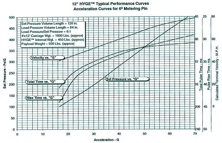
System Performance
Typical System Layout
click image below to view larger image in new tab.